Product Description
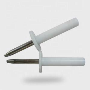
The Rigid Test Finger is a precision test probe made according to Figure 7 (Fig. 7) of the IEC 61032 (Test probe 11) and is used to simulate a human finger. It is also used by the standards of IEC 60335, IRAM 4220-1 and in most of the rules involved in the verification of accessibility to live parts.The Rigid Test Finger was made on stainless steel and Polyamide handle.
Applicatiopn
1.The joint part of The Standard Test Knurled Finger Probe can't touch the live parts or close to the dangerous parts, and 50 mm to 20 mm baffle plate cannot enter.
2.In the prevent electric shock test, wires , power devices, and lighting devices are needed.
3.Both joints shall permit movement in the same plane and the same direction through an angle of 90° with a 0° to +10° tolerance
Technical Parameters
| Nodular Finger length | 80mm |
| Nodular Finger diameter | 12mm |
| Dam-board diameter | 50mm |
| Dam-board thickness | 5mm |
| Material | delrin and stainless steel |
NOTE 1:Using the pin and groove solution is only one of the possible approaches in order to limit the bending angle to 90°. For this reason, dimensions and tolerances of these details are not given in the drawing. The actual design must insure a 90° bending angle with a 0° to + 10° tolerance.
NOTE 2: Dimensions in parentheses are for information only.
NOTE 3: The test finger is taken from IEC 60950-1, Figure 2A. That test finger is based on IEC 6103216), Figure 2,test probe B. In some cases, the tolerances are different.